 |
||||
 |
||||
 |
||||
Net Dynamic Menu by Vista-Buttons.com v4.3.0
We are listed on and
|
AutopilotsBy Captain Scott FratcherAutopilots, known affectionately as “Otto,” or “my silent crew,” or even “dial a ride,” have been around for over fifty years. Now considered basic safety gear, the ability of the crew to hold a course without the need for a crewmember manning the windswept helm has made the autopilot standard equipment on most offshore yachts and serious fishing boats. Autopilots allow short handed crew to single hand when needed while single handed sailors can catch short bursts of sleep. Racing teams have found autopilots have a better record of holding course than a tired helmsman, and fishermen can concentrate on reeling in the catch while the launch lumbers slowly along guided intelligently, preventing a line tangle.
Autopilots fall in to three basic categories-• Portable, stand alone, above deck units Let’s look at each system in turn
Above deck autopilotsSmaller yachts and launches (up to 40ft) can often survive on a simple, stand alone electric autopilot bought from a local chandlery. These industrial work horses have come a long way in the last twenty years since the first “Tiller Pilot” arrived on the market. Made for both wheel and tiller steered boats, they are dependable and energy efficient. With a starting cost under 1000NZD it’s no wonder most every small yacht has adopted and often named an electric self steering device. Above deck autopilots are built waterproof, with a thrust of over 80kg, and self learning. In other words a modern autopilot will quickly learn the response needed to steer each individual vessel preventing over correction and slewing. New units contain an internal fluxgate compass, and can be mounted port or starboard depending on available space. A few extra wires and they interface to a GPS or wind monitor, all for an electrical draw of an amp or two. Most units have one touch “lock on compass course” or GPS waypoint tracking. Push two buttons at the same time and the boat tacks leaving a small crew free to handle sheet lines and winches. Higher quality autopilots have “man overboard retrieval” programs and downloadable data packs. Handheld remote controls allow the crew to move around the boat while
adjusting course, dodging obstacles or even holding an accurate course
while reefing.
WheelpilotAbove deck wheelpilots are available for smaller yachts and launches with the same functions as the tillerpilots, they just couple directly to the boat’s wheel instead of the tiller. Installation is quick and can be performed by most DIY’s in a day. Keep in mind most small wheelpilots are belt driven or direct coupled to the wheel. This means the wheel must turn perfectly true. Even a small amount of wobble in the wheel or a slightly bent steering shaft will quickly break the belt or ruin the drive gears in a direct coupled wheelpilot system. Note-Adding a Wheelpilots to an old steering system demands a complete inspection of all steering components. Wheelpilots can develop tremendous force and don’t have “intuition” if they are over stressing any part of the steering system. Old bushings, cables, and support arms can quickly wear with the addition of a new wheelpilot.
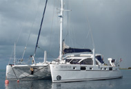
Below deck autopilotBelow deck autopilots are the all weather answer to boats over 40ft.
The components are split into four sections- Let’s look at each component in turn.
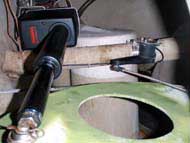
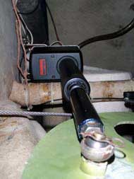
Drive unitThe drive unit is the working end of the autopilot. It does the actual work of moving the rudder. The drive is typically linear, or push/pull of mechanical or hydraulic style and can exert incredible force. Consider the power on the tiller of a medium sized yacht. If you choked up the tiller till you were just a half meter from the rudder stock it would be near impossible to control the helm due to the high loads involved. This is a basic example of the forces involved in trying to steer a large yacht with a linear drive and why the installation must be thought out and robust. The most often overlooked aspect of a drive unit installation is the securing method of the drive base to the boat. Any mounting flange movement will cause “wallowing” of the bolts leading to an early failure. Tip-Most drive units come with holes to accommodate four large bolts. To increase the strength consider building a stopping block, or lip around the mounting flange so the auto pilot flange has something to butt against. During installation it is important to check that the drive unit has a small amount of excess available movement past the swing of the steering quadrant. We don’t want the drive to act as a rudder stop. The connection to the rudderstock can be through the existing steering quadrant, or better is a separate, keyed arm attached to the rudder stock. This second arm gives a true backup steering system for the yacht. The load on an autopilot drive can be high especially during rough weather. While the average current draw might be three amps, the drive motor uses short bursts of high current that average to a three amp draw, thus large wire should be used to feed the drive unit motor. Check the wire size charts to be sure of a maximum 3% voltage drop during the high intermittent loads. Remember-low voltage increases amp draw, shortening the life of the drive motor. The autopilot drive should have its own breaker (not a fuse) direct to a reliable power source such as the main power bar in the electrical panel. Resist the urge to tap into an existing power source such as the spotlight etc. Hydraulic drive unitsHydraulic power packs are simple, robust and often used in larger autopilot installations or outboards. Yachts with existing hydraulic steering systems may simply add a hydraulic power pack T’ed into the existing hoses. If the vessel has an existing conventional steering system going hydraulic means adding a balanced steering cylinder in addition to the powerpack. The forces can be regulated through cylinder size and system pressure. Like a linear drive unit, hydraulic cylinders need stout mounting and an even stronger connection to the rudder shaft. Hydraulic systems have very little give and don’t tend to back feed. This means the rudderstock, quadrant and connections all must be able to support the full load of a breaking wave or grounding. Central processing unit (The brain)The central processing unit (CPU) of the auto pilot is often considered the brain. Modern central processing units interface with GPS and NMEA signals and have learning programs that quickly adjust to sea state and boat movement. Note-While wind and compass data can be gained through the use of NMEA, or the existing wind instruments, most NMEA inputs take a few seconds to cycle through the NMEA code thus the input is not fast enough for auto pilot response. For this reason it’s important the autopilot CPU have its own compass and wind sensors. In the old days the CPU simply monitored the course and turned the helm to make corrections. This used a lot of power and caused the boat to zigzag up along the course line. Today the CPU can be programmed for the type of boat, speed, acceleration, and type of use, IE fishing, racing etc. Modern CPU’s even sense lateral movement to know when the boat is “slewing” down a wave. This is done through a new gyro style sensor based on a low cost sensor similar to the anti shake feature used in most video cameras.
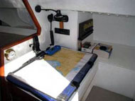
InstallationThe CPU should be mounted below decks in a clean, dry, cool area. The CPU can build up considerable heat so airflow is a must. Drip loops should be built into the wire ways to prevent water following a wire into the circuit board.
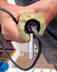
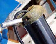
Rudder angle indicatorThe rudder angle indicator is device that tells the computer where the rudder is pointed. It also can give an idea of the speed the rudder is reacting to the commands. The rudder angle indicator is mounted next to the drive unit with its own connection rod to the quadrant and electrical cable to the control head. The rudder angle indicator is often considered a weak link in an autopilot installation. They tend to be fragile and can be ruined by an errant foot or a careless line tossed over them. Most professional installers build a guard over the delicate components for long term reliability. Some modern systems, such as Simrad, have virtual rudder angle indicators for use on outboard motors eliminating the need for this extra piece of gear and extra wire.
CompassThe CPU needs to know where the boat is pointed. This information is supplied by use of a fluxgate compass. The location of the compass should be away from metal, and electrical cables. Note- Place placards or signs around the compass so crew will know the location when storing supplies. Keep an eye on the location of stored goods such as steel dive tanks and canned food that can create, or disturb the magnetic field around the compass. Swinging the compass is a simple task of driving the boat in a slow circle (follow the manufacturers instructions) while the computer makes corrections. During the swinging of the compass be sure to have all high load devices turned on so if interference is present the computer will attempt to compensate.
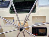
Control headThe control head is the interface between the sailor and the autopilot. Careful thought should be applied when deciding on the type of display to purchase. Most systems allow a variety of displays to be used. A choice between a rotating knob, push buttons or even a remote control can be ordered depending on the desire of the user. Control heads are similar to a remote helm and can be installed in place of separate steering stations saving space and money. Consider a second control head at the navigation station, or near the fishing area of the boat. Tip-A repeater unit mounted in the skipper’s bunk can provide peace of mind. Some repeaters have NEMA outputs so the skipper can control the helm, and monitor the wind speed all from the comfort of his bunk.
SSB Radio InterferenceSSB radios are notorious for causing interference that can cause an autopilot to “wonder”. Many a yacht has been lost when the skipper went below to announce his arrival to friends over the SSB. The autopilot course was interfered with by the radio signal causing the boat to veer off course ending a grounding. Once the autopilot is installed test the system in open, safe water by making a series of broadcasts on the SSB proceeding through the various bands verifying there is no interference. If the yacht is using a Pactor modem for email repeat the procedure on high power through the Pactor modem.
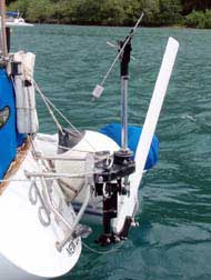
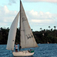
WindvaneWind vanes are the old yacht standby. They are tough, don’t use any electricity and can be fixed with a basic welding machine in most outback locations. In today’s world of high technology, and low autopilot electrical draw, fewer yachts tend to rely on the old windvane. A quick survey of yachts crossing the Pacific this year showed only about 30% had even bothered to install a windvane and less admitted to using them.
This low usage rate is for three reasons-
|
Articles originally published
in
|


|
||||
|
||||
| © Team Yachtwork 2009 |